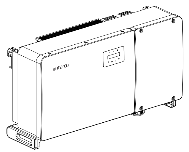
This page describes the communication with an Autarco OX-series on-grid inverter over Modbus-RTU (rs485).
By default, the inverter is set to address 1.
The OX inverters have the following communication ports:
COM1: Green 4 pin connector for WiFi/Cellular datalogger.
COM2 and COM3: Cable glands and cover with following connection points behind:
2 x RJ45 connections
1 x RS485 terminal bloc
Specifically for the SmartgridOneController, the RS485 communication happens over the 'COM2 Terminal Block' port. This marked in the orange box in the image below:
The port is an RJ45-port, used for the RS485 communication.
A cable need to be prepared to connect the inverter to the inverter.
Insert the wire into the RJ45 connector then crimp the connector with the crimping tool.
Removethe cap nut from the waterproof cable glands labeled COM2 and COM3 at the
bottom of the inverter. Remove the plug from the fitting.
Insert the RJ45 connector into the RJ45 port in the inverter maintenance chamber.
Replace the cap nuts for COM2/3 and tighten firmly.
You MUST give each devicea unique address on the RS485 bus. Check the device manual for instructions.
Use lower addresses first (1, 2, ...) because the SmartgridOneController will find them faster!
For each device, it is generally recommended to keep the factory-default baud rate, parity, and stop bits. The SmartgridOneController will scan those first.